Data
- The meaning of self-lubricating bearings
The so-called non-lubrication means that there is no or no lubrication, and the goal of our research is to ensure that the bearing still performs well under various operating conditions and that its service life is extended as much as possible. The basic working principle of self-lubricating bearing is that in the initial operation stage, the solid lubricant on the surface of the bearing forms a transfer film due to friction between each other and is coated with the grinding parts, and finally forms a solid lubricating film to achieve the purpose of self-lubrication, which isolates the direct contact between the workpieces, so as to protect the grinding parts well and extend the service life of the bearing and the workpiece.

- PV Value Calculation for Bearings - Definition
○ Load pressure P: defined as the load divided by the positive projection area of the bearing bearing surface (unit: N/mm²);
○ Running speed V: defined as the relative linear velocity on the dual surface (unit: m/s);
○ PV value: defined as the product of bearing pressure P and velocity V (unit: N/mm · m/s);
○ Allowable maximum PV value: Allowable maximum pressure P× allowable maximum speed V (unit: N/mm²·m/s).
- Calculation of the PV value of the bearing - the maximum allowable PV value
○ When the PV value reaches the limit value, the bearing can be operated for a short time. In continuous operation, the choice of the maximum allowable PV value depends on the requirements of the operating life. Design requirements: maximum allowable PV value, allowable maximum pressure P* allowable maximum speed V. See the image below:

- The design of the matching housing bore - straight sleeve bearing
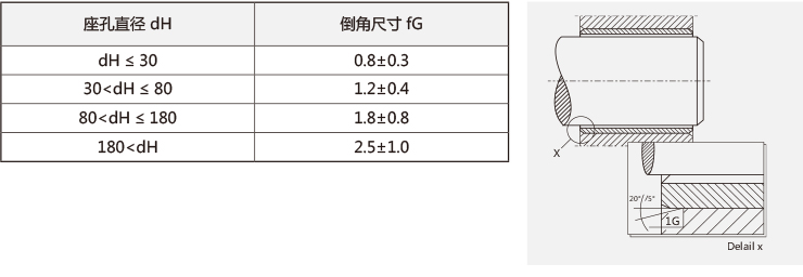
In order to facilitate bearing mounting, the mating housing bore must be chamfered.
1) Straight sleeve bearing
○ The matching seat hole should be chamfered fG×20o ±5o, and the size of fG should be based on the diameter of the seat hole dH.
- Matching housing bore design - flange bearing
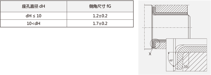
In order to facilitate bearing mounting, the mating housing bore must be chamfered.
2) Flange bearings
○ For flanged bearing mating housing holes, the housing bore is required to provide a chamfer large enough to prevent deformation at the flanging radius of the flanging bearing. Matching seat hole chamfer fG×45o ±5°
- The design of the matching shaft
○ The performance of self-lubricating bearings is largely affected by the surface roughness, hardness and surface plating of the mating shaft material, and the high-quality mating shaft surface can prolong the life of the bearing, on the contrary, the rough mating shaft surface will reduce the life of the bearing.
- Design of mating shaft - surface roughness of mating shaft
○ a) When the surface roughness of the mating shaft is large, the convex part of the shaft and the bearing will cut off the oil film, resulting in direct contact between the two, so the surface of the mating shaft is required to be mirror-processed, so as to reduce the oil film gap as much as possible, so that it is close to the state of fluid lubrication, so that the bearing performance can be improved.
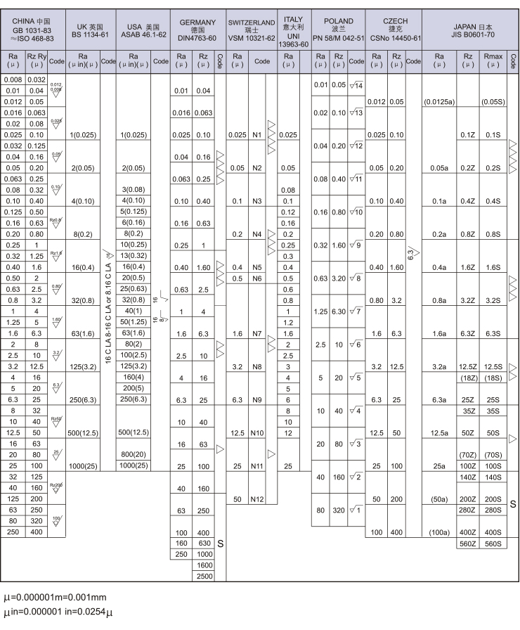
○ b) Most self-lubricating bearings are used under dry friction or boundary lubrication conditions, and do not need to require mirror processing on the surface of the mating shaft as under fluid lubrication conditions, as long as the surface roughness of the mating shaft is controlled in the range of Ra=0.32~1.25.
- Design of mating shaft - mating shaft hardness
○ When there is no intrusion of hard impurities, good results can be obtained by using the shaft material and hardness recommended in the table below; Instead, use a mating shaft material with a higher degree of hardness whenever possible.

○ Under the condition of high load and swinging movement, the matching shaft must be heat-treated, and the hardness after heat treatment is inferred according to the material.
- Design of mating shaft - surface treatment of mating shaft
The purpose of mating shaft surface treatment is to:
a) Improved corrosion resistance
b) Improve surface hardness
c) Smooth the surface and improve lubricity.
c) Plating on the mating shaft can improve its corrosion resistance, and effectively reduce rough friction and improve lubricity; When the mating shaft is rusted, the invading of hard oxides and foreign matter is also one of the causes of wear, so it is recommended that users plating hard chrome on the mating shaft. Under similar corrosive conditions, such as seawater, mating shafts must be plated with two to three layers of hard chrome.
- Design of mating shafts - Mechanism design of mating shafts
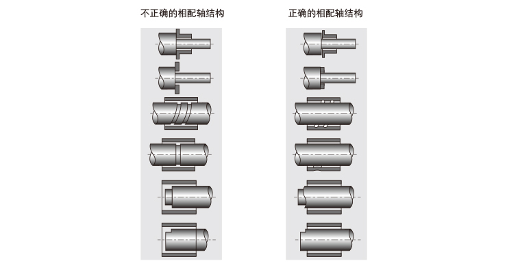
○ The rough surface of the mating shaft, sharp corner burrs, and grooves will damage the sliding layer, as shown in the figure below:
- The same factor that affects the life of the bearing
○ The life of self-lubricating bearings, except for intense scorching, is usually determined by the wear of the inner diameter of the bearing. Self-lubricating bearings are used in dry friction, boundary lubrication, and fluid lubrication, and their wear conditions vary greatly. The main factors that determine the life of self-lubricating bearings are: load characteristics and direction, lubrication conditions, operating speed, ambient temperature, mating shaft hardness, mating surface roughness, mating shaft material, the properties of the surrounding air (gas), etc., so it is very difficult to find the exact wear amount through calculation.
○ Without considering the influence of speed and load on the bearing, the difference in the direction of movement of the bearing, the type of lubrication, the size of the mating clearance, the surface roughness and the --- of the magazine penetration, etc., the empirical formula for calculating the wear amount W can be given:
○ W=K· P· V· T (mm)
○ P: Load pressure (N/mm²)
○ V: Running velocity(m/s);
○ K: Abrasion coefficient (mm/ (N/mm² · m/s · hr))
○ T: Running time (hr)
○ Under different lubrication conditions, the value of the wear coefficient K obtained by the experiment is shown in the following table:

- Assembly of bearings - Formula for calculating the press-fit force F during assembly

○ t: Basic thickness (mm) after removing the composite layer
○ b: Bearing height (mm) △: Stress coefficient = 1.9×10⁵ (N/mm²) B
○ бmax: interference (mm)
○ D: Bearing OD (mm)
○ <Note >: At this time, the friction coefficient between the outer circle of the bearing and the inner circle of the housing bore is usually about 0.15.
○ Examples:
○ PU-1 2015 (standard product) Press into the seat hole of φ23
 , and find the amount of press-in force F at this time.
○ Calculation:
○ The thickness of the wall is SB=1.5mm, the thickness of the composite layer is 0.3mm, and the thickness of the substrate is t=1.5-0.3=1.2mm; Bearing height b=15;Bearing outer diameter D=23mm; Interference бmin=0.014mm, interference бmax=0.075mm.

○ Therefore, the press-in force F=1880~10040N during installation
- Bearing assembly - sleeve assembly method
Assembly method
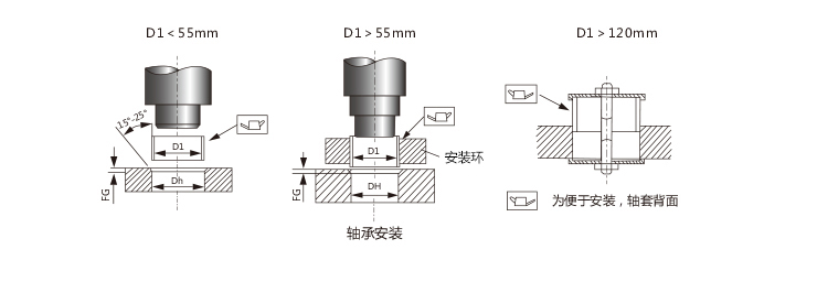
1) Assembling method of straight bearings
○ The diameter of the mandrel guide rod is 0.1~0.3mm smaller than the diameter of the mounted bearing. The mandrel is best heat-treated. In order to facilitate press-fitting, a little oil can be drawn on the outer diameter surface of the bearing, and do not press it in by impact methods such as directly hitting the end face of the bushing with a hammer; When installing large diameter D>55mm bearings, measures must be taken to calibrate the bearing seams.
- Bearing assembly-flanging assembly method
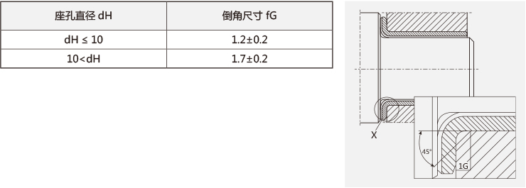
In order to facilitate bearing mounting, the mating housing bore must be chamfered.
2) Flange bearings
○ For flanged bearing mating housing holes, the housing bore is required to provide a chamfer large enough to prevent deformation at the flanging radius of the flanging bearing. Matching seat hole chamfer fG×45o ±5°
- Bearing assembly - thrust gasket, plate assembly method
Assembly method
3) The assembly method of thrust gasket and flat plate
○ We recommend the use of fixed pins, countersunk nails to install thrust gaskets, and the use of inlaid mounting plates. When installing thrust gaskets or plates, the lubrication layer is required to be 0.3~0.5mm thick higher than the base.

- Inspection method of rolled bearing - inspection method of outer diameter of wrapped bearing
1. Inspection method for the outer diameter of the rolled bearing
1) Pressurized test method (according to DIN1494-2 test method A)
○ The test tire is composed of two semi-circular test dies, during the inspection, the zero position is calibrated with the calibration mandrel dch.2, the slit of the bearing is placed on the top of the test die, and then the two halves of the die are applied to each other to the test load Fch, and the distance △z of the test die is obtained by the reading device.

2) Environmental gauge test method (according to DIN 1494-2 test method B)
○ The inspection adopts the through and stop ring gauge for testing, and the bearing can be pushed in and passed by hand (maximum force 250N); Under the same force, the ring gauge cannot be entered. Note: In some cases, e.g. if the wrapped bearing is not round or the seam is too large, the inspection accuracy may be affected.

3) Ruler detection method (according to ISO3547-2 test method D)
○ In order to measure the outer diameter of a large bearing, the circumference of the circle can be measured with a ruler. Use a measuring tape ruler 360° along the midline of the bearing width along the bearing to apply sufficient tension to close the opening. The measuring tape ruler is calibrated around the locating mandrel whose outer diameter is equal to the nominal outer diameter of the bearing. The indicator is placed at the free end of the measuring tape and adjusted to the calibrated size. After the bearing inspection is completed, the circumference indicator reading △ZD should be the difference between the measured value of the bearing and the calibration value of the positioning mandrel. From this, the outer diameter of the bearing can be calculated.

- Inspection method of rolled bearing - inspection method of inner diameter of wrapped bearing
2. Inspection method for the inner diameter of the rolled bearing
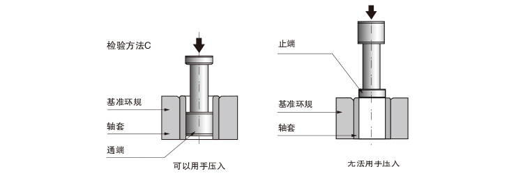
1) Plug gauge test method (according to DIN 1494-2 test method C)
○ Press the wrapped bearing into the H7 median ring gauge, and use the plug gauge to detect the inner diameter of the bearing.
2) Micrometer detection method for wall thickness
○ Use a wall thickness micrometer to measure the wall thickness of the bearing to indirectly calculate the inner diameter of the bearing. Note: According to DIN1494-2, it is important to remember that the wall thickness and bore diameter of the test bearing cannot be marked on the drawing at the same time.
- Inspection method of rolled bearing - inspection method of thrust plate
2. Inspection method for the inner diameter of the rolled bearing
1) Plug gauge test method (according to DIN 1494-2 test method C)
○ Press the wrapped bearing into the H7 median ring gauge, and use the plug gauge to detect the inner diameter of the bearing.
2) Micrometer detection method for wall thickness
○ Use a wall thickness micrometer to measure the wall thickness of the bearing to indirectly calculate the inner diameter of the bearing. Note: According to DIN1494-2, it is important to remember that the wall thickness and bore diameter of the test bearing cannot be marked on the drawing at the same time.

- Surface roughness comparison table
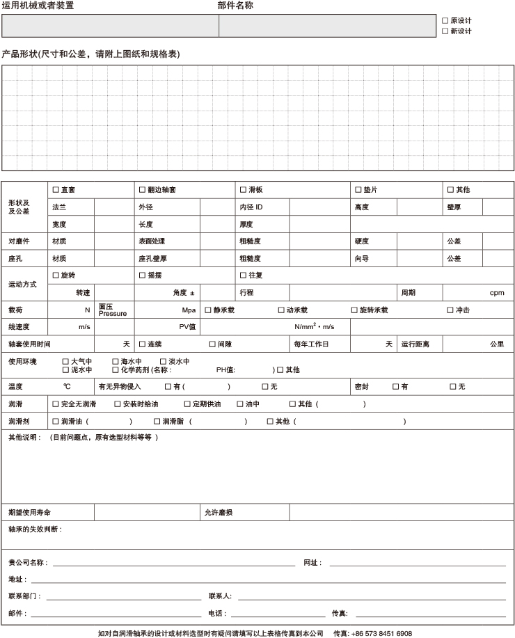
- Plain bearing technical parameters consultation form
